Sunday, June 7, 2015

2-June-2015: Oscillations and "Small" Theta


Purpose: 

To find the period of multiple objects swinging back and forth on a pivot with a small change in theta.
We want to use the restoring force and small theta of the oscillation to manipulate our equations so that we can find the period of oscillation of a swinging object and then compare it to the experimental recording of the period.

Set Up:

For the experiment, we put the object onto a pivot and let it swing back and forth slightly.

A piece of tape was attached at the end of the object that would pass through a photogate to record the time of each period through LoggerPro. 


Experiment:

1. Since we already had the steel ring for the first part of the experiment, we just needed to make a thin semi-circle and an isosceles triangle out of styrofoam. We did this using a saw in class!


2. Next we needed to measure the necessary elements of each object needed in later calculations (steel ring and styrofoam shapes):


Mass of Steel Ring = 396.8 grams


Measured Data Recorded:

Solid Ring
Inner Radius = 0.1390 m
Outer Radius = 0.1154 m
Mass = 0.3968 kg

Isosceles Triangle
Base = 0.1931 m
Height = 0.1508 m

Semicircular Plate
Radius = 0.0983 m 

3. Now for the next fun part, performing the experiment! 

First we tapped the steel ring so that it oscillated back and forth (shown in the set-up) and found its period by looking at the mean of the data from photogate and LoggerPro:

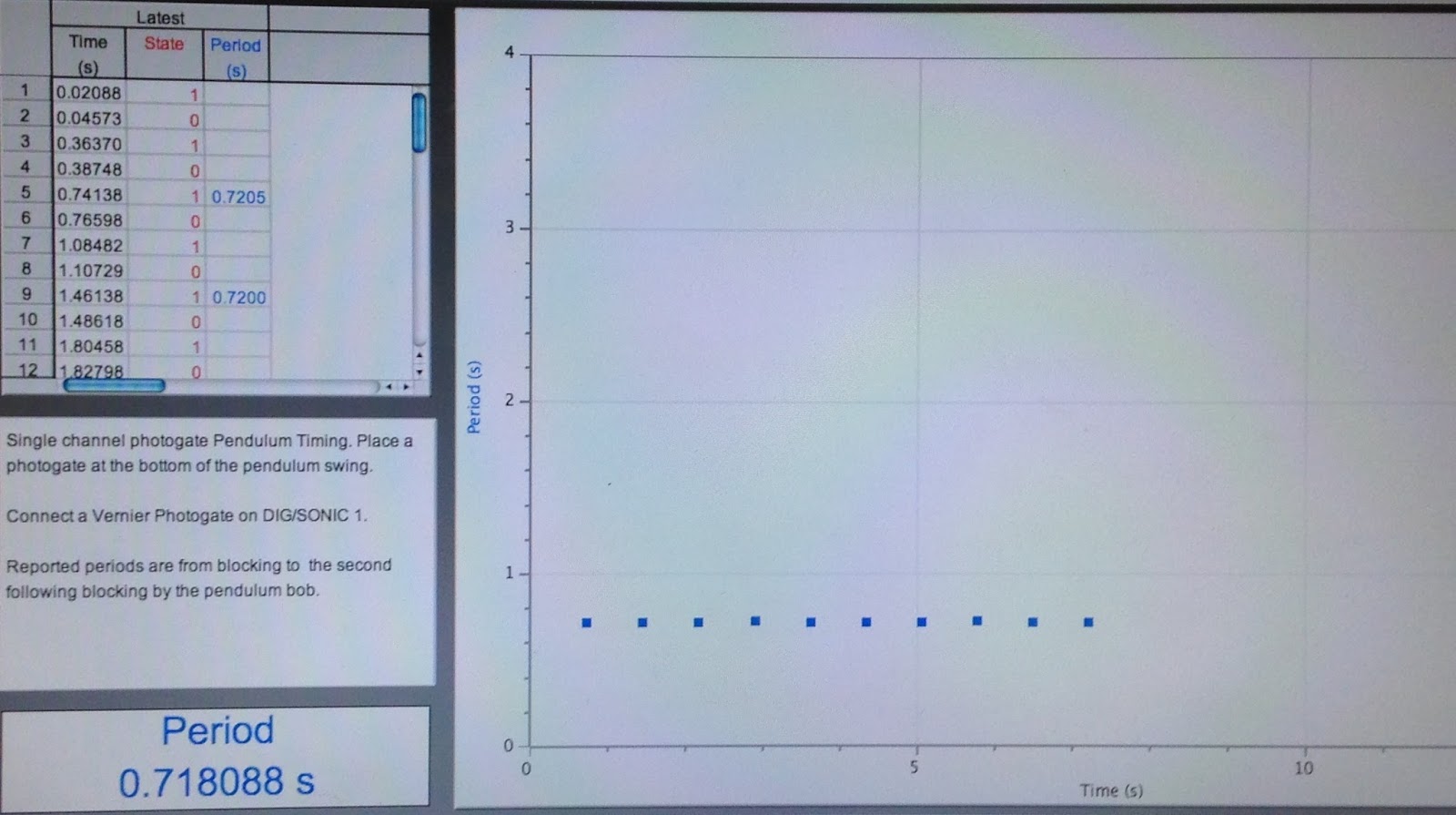
Period = 0.7181 seconds

Second we attached two aluminum loops on each side of each styrofoam shape to put a paper clip through, which that was taped to the stand. We tapped the styrofoam shape a small theta so that it swung back in forth in an oscillating motion, recording the period with photogate and LoggerPro and used it to find the average period by looking at the mean of the data:

Semi-circle concave up:
                                                                            Pivot at the center of its base


Period = 0.6838 seconds

Semi-circle concave down:


Period = 0.6789 seconds
Triangle right-side up:


Period = 0.7843 seconds 
Triangle up-side down:


Period = 0.6789 seconds


Data Analysis:

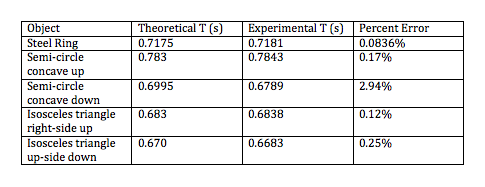
Using our measured data, we now could calculate the theoretical period and compare it to the experimental period. 

The Steel Ring

First we needed to find the new inertia of the ring. After finding the average radius we able to calculate the new inertia since we now knew the linear shift. 

Inertia of the Steel Ring in this case = 3.23 * 10^-3 kg *m^s
Next we used Torque = Inertia * Angular Acceleration so that we could manipulate it into giving us the period of the Steel Ring's swinging. 

In this case Torque = mg * avg. radius * sin(theta) as well, where sin (theta) is so small it can written as just Torque = mg * avg. radius * theta

Theoretical Period = 0.7175 seconds

The semi-cirlce concave up

First we calculate the inertia and find the center of mass:

Next we calculate the theoretical period by applying Torque = Inertia * Alpha once again:


Period = 0.683

The semi-circle concave down

Now that we are rotating the semi-circle at the top of the round edge, we need to shift the moment of Inertia:


Now that we have the new moment of inertia that we found by using Euler's law (shifting the inertia of the center of mass linearly), we can find the theoretical period:


Period = 0.67 seconds

The triangle right-side up

First we calculated the inertia using methods of integration (pivot was at the tip of the triangle):


Next we found the period of the triangle using T=I*alpha:


Period = 0.783 seconds

The triangle up-side down

Last but not least, we found the inertia of the triangle pivoted at the center of its base, in this case we were able to use integration once again and substitute the y for H-y since the triangle was just being flipped:


We found the period for the last time using T=I*alpha:


Period = 0.6995 seconds


% Error:

Example:

Steel Ring
|(0.7181-0.7175)|/0.7175 x 100% = 0.0836% error

Overall:


Conclusion:


With an overall average percent error of less than 1% our experiment was successful is showing that due to the restoring force of the swinging and the small oscillations, we were able to make sin theta into theta, therefore simplifying our equation which allowed us to find the angular velocity using the equation angular acceleration = angular velocity^2 * theta. Therefore, we were able to derive and find the theoretical period successfully. Error may have come from friction on the pivot, making sin theta into theta (less accurate to the smaller decimal place), and pushing the object too much creating a theta that was larger and greater affected by changing sin theta into just theta.


Wednesday, May 27, 2015

20-May-2015: Conservation of Energy/Conservation of Angular Momentum

Purpose:

To release a meter stick, pivoted at one end, so that it swings and collides inelastically with a blob of clay and to record the height the clay at the end of the stick reaches.

To find the theoretical height the clay reaches using calculations from conservation of energy and conservation of angular momentum.

To compare these results.

Set-Up:

The apparatus consist of a meter stick hanging from one pivoted end and piece of clay with tape of negligible mass wrapped around it so that the meter stick inelastically collides with the clay.

Clay lined up so that it's cm is nearly at the very tip of the stick


Experiment:

1. First we needed to collect all the measurable data such as the weight of the clay and meter stick at its center of mass.

Mass of Clay = 25.3 grams


2. To perform the experiment we lifted the meter stick until it was parallel to the ground and set our pivot point as our GPE=0.


3. We then recorded, on video capture, the dropping of the meter stick going from full GPE to all KE and then inelastically colliding the piece of clay, rising a specific height. 

Data Analysis:

1. To start, we analyzed the video capture data to figure out how high the meter stick raised after inelastically colliding with the piece of clay, shown below: 

Height of clay reached above the ground = 0.2904 meters

2. Next we needed to find the theoretical height the clay would reach through analyzing the scenario through three separate phases.

First, we looked at the switch of energy from potential to kinematic of the meter stick to find the angular velocity of its center of mass, just before the collision with the clay. 

Omega of Ruler = 6.067 rad/s
Second, we used this omega as the initial omega and used momentum to find the final omega after the collision of the mass and clay. 

Omega of Clay and Ruler = 3.170 rad/s
Lastly, we looked at energy again to find the angle theta that the meter stick would rotate, using that to find the theoretical height reached by the clay after the collision.

Theoretical height reached by clay = 0.401 m

% Error: 

|(Theoretical height-Actual height reached by clay)|/Theoretical height *100% = percent error

|(0.401-0.290)|/(0.401) * 100% = 27.58%

Conclusion:

When finding the theoretical height through conservation of energy and angular momentum we estimated the clay to rise 0.401 meters off the ground when in reality it rose 0.290 meters. Although our percent error was roughly 25% off, it was not surprising the actual height reached would be less than predicted. Although the energy was conserved, there were many factors not taken into account when finding the theoretical height, such as loss of energy due to heat and friction of the pivot (let alone human error such as not using the correct number of sigfigs). The experiment was successful is proving to us the conservation of angular moment and conservation of energy. 


Tuesday, May 26, 2015

18-May-2015: Moment of Inertia and Frictional Torque of the Big Wheel

Purpose:

Part 1: To find the frictional torque of the big steel wheel.

Part 2: To use this torque to find inertia of the wheel, that'll be used to then predict the time it takes for a cart to drop a meter that is attached to the wheel by a string wrapped around it.

Part 1: Finding the Frictional Torque

Set-Up:

The wheel being turned actually has three parts, the outside cylinders and the main wheel in the middle.


Experiment:


Over all, to find the frictional torque we need to find the angular deceleration of the wheel and the Inertia of the wheel.

1. To find the angular deceleration we set up a video capture on logger pro, using the camera shown above. This video would then be analyzed to find the angular deceleration of the wheel after we spin it.

2. To find the moment of inertia, we needed to measure the radius and mass needed, and then calculate it.

Data Analysis:

1. Using the video we marked every revolution recording it's time with video analysis, giving us revolutions per seconds or omega.

Blue Dots Represent Each Revolution
Next then plotted omega vs time to find the slope as our angular deceleration (where omega was translated into rad/s):
Angular Accerlation = -0.3768 rad/s/s


2. Since inertia depends on mass and how far it is from the center of rotation, we had to find the radius of each cylinder and the according mass shown below:


Since inertia for a disk is  I=.5mr^2, we were able to plug our values of radiuses and masses to find the inertia of the rotation apparatus:


Now that we had inertia and angular acceleration, we are able to find the frictional torque using Torque = Inertia * Angular Acceleration.

(where the y= represents the translation from slope found above into alpha)


Part 2: Finding time of Cart Going Down a Slope for 1 Meter

Set-Up:

We set up a ramp in which the cart attached to a string would roll down. The string would also be wrapped around the big wheel, rotating the whole mass of the big wheel and the two cylinders on each side:


Experiment:

We then recorded the measurable data needed in calculating a predicted time, recording the angle the ramp was at and the weight of the cart.

We then ran the cart down the ramp for one meter three times each and recorded the time it took.

Data Analysis:

We then calculated the predicted, "true" value of the time the cart should take in rolling down the meter ramp by taking the torque of the cart and subtracting the frictional torque and setting that equal to the inertia of the big wheel and it's angular acceleration. Since the acceleration was the unknown that would help us find time, we had to derive an equation to find it using the force equation of the cart and assuming that the acceleration of the cart and the tangential acceleration of the big wheel were the same. Calculations show below:

If you look above, the experimental values are also shown below the calculated time of 7.34seconds.

Conclusion:

In considering factors such as assumptions being made like acceleration of the cart being exactly the same as the tangential acceleration of the wheel as well as a possibly incorrectly recorded frictional torque (uncertain due to possible measuring errors and inaccurate video analysis), we compared our results:


With a percent error less than 5% we successfully completed our experiment, realizing how to find frictional torque and a mass' inertia and using these properties to find the tangential acceleration of that mass if a torque was applied it. 


14-May-2015: Moment of Inertia of a Uniform Triangle


Purpose:

To experimentally determine the moment of inertia of a right triangular this plate around its center of mass, for two perpendicular orientations of the triangle.
To then determine the "true" moment of inertia through calculations.
To compare our results.

Set-Up:

We mounted on a holder and disk onto the rotating system. The upper disk floated on a cushion of air to avoid friction. A string was wrapped around a disk attached to the upper disk and the triangle so that when the other end of it fell with a light mass, the string unraveled and turned the system providing torque. The torque pulley, disk and holder are shown below:


System without Triangle
We would then add the triangle onto the holder:


System with Triangle
Experiment:

1. First we set up the experiment so that we could find the angular acceleration of the rotating disk and holder when the light mass is dropped and provides a torque. Therefore, this will be used to find the inertia of the system without the triangle.

Angular Acceleration of Upper Steel Disk and Holder


2. Next we will need to collect the measurable data which included the mass of light mass, radius of the turning disk where the torque occurs, length, width, and weight of the triangle:


Mass of Light Hanging Mass
Radius of Disk with Torque

Width of Triangle

Length of Triangle

Mass of Triangle

Overall Recorded Measured Data: 

3. Next we performed the first step of the experiment so that we could find the angular acceleration of the rotating disk and holder with the triangle vertical when the light mass is dropped and provided a torque.

Angular Acceleration of Upper Steel Disk, Holder, and Vertical Triangle


4. Lastly, we recorded the angular acceleration with the triangle horizontal


Data Analysis: 

1. First we need to organize our angular accelerations. To find the angular acceleration we looked at the slope of the graph of angular velocity. Realizing that there is still slight friction between the steel disc even with an air cushion, we needed to take the average:

(rad/s/s)
2. Now that we have angular acceleration we need to know it's relationship to Inertia:

Torque = Inertia * Angular Acceleration

We are able to find the experimental Inertia of the Triangle by subtracting:

Inertia of System with Triangle - Inertia of System without Triangle = Inertia of Triangle

Using the same method from the previous experiment, we used our derived equation to find Inertia:


Next we are able to find our experiment's Inertia equation using the measured data:

mass of light mass = 24.5g (switch g to kg in the picture)
radius of disk with torque = 2.25cm

Experimental Inertia's found:


3. Lastly, we found "True" Inertia's of the vertical and horizontal triangle.

We first had to find the moment of inertia for a triangle being spun around it's edge:


Next we used Euler's law of motion to find the moment of inertia of a triangle rotated about its center of mass:


Using this equation we were able to plug in the vertical and horizontal data to find the "true" moment of Inertia:


Conclusion:

Comparing the results of the experimental inertias to the "true" calculated interias, we found this percent error:


This shows that our experimental values and calculated values were very close, a successful data analysis. Although uncertainties may have occurred with taking the measurable data or not getting a close enough angular acceleration reading, our results proved that moment of inertia can be found through correct integration, just like we have been doing in class, and reflect "real-world" experimental results.