Saturday, April 25, 2015

15-April-2015: Impulse-Momentum activity

Part 1

Purpose:

To observe collision forces that change over time (observing the Impulse-Momentum theory).

Impulse is:
J = Force * ∆time

Impulse can therefore be represented by the area under a graph of Force versus time. 

In the Impulse-Momentum theory, impulse also equals the change in momentum so that ∆p = J.

Experiment: 

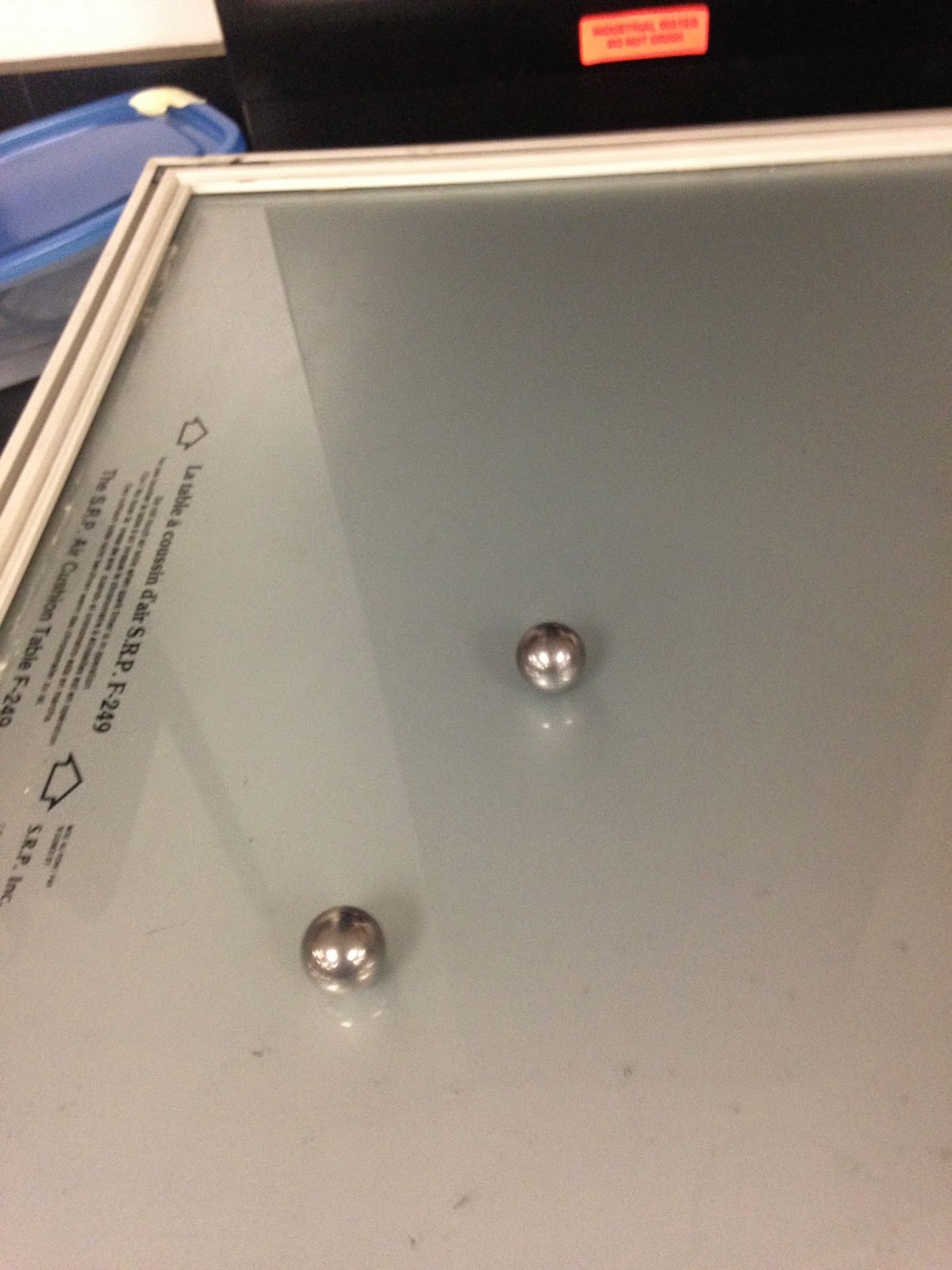
To observe this theory we set up a cart and plunger apparatus.

Pluger and Cart
1. First we clamped the dynamics cart to a rod and clamped it to the table (plunger/blue cart).

2. Then we mounted a force sensor on another dynamics cart so that the force sensor hook mounted the protruding part of the blue cart. 

3. We then set up a motion detector behind the car to measure the velocity versus position function (not shown in picture). 

4. We then made the carts collide several times to observe what happened to the spring plunger. 

5. To make sure we had good data before collecting it analyzing it, we made sure that the track was leveled so that momentum was conserved, friction was negligible, and that the force sensor was zeroed before the collision. 

Data Analysis:

Once we did the experiment, we now had the data of the position and velocity of the cart from the motion detector and the force of the collision versus time from the force sensor. 

Using the velocity, we could make a momentum column using the equation p = m*v

The momentum of the cart needs its mass, which is shown below:
mass = .684 kg
We then were able to make a column for the momentum of the cart:

Momentum of the Cart Column Equation
We then graphed the momentum versus time and put it on the same graph as the Force versus time.

We then took the integral of the force graph to find Impulse, which should equal momentum. 

Initial Momentum and Overall Impulse

Final Momentum and  Overall Impulse

Looking at the graphs, the first one shows the initial momentum and the second shows the final momentum while both graphs have the integral of the Force graph as well. 

The integral of the force graph gave us an impulse of J = 0.5170 N*s

Comparing this to the change of momentum we got:
P final - P initial = 0.224 - (-0.264) = 0.488 kg*m/s  

The percent error for this experiment is:


In this experiment, the collision is nearly elastic. In an elastic experiment, the initial momentum would be exactly equal to the final momentum, just in opposite directions. The 5. 61% error proves that although some momentum is lost, due to momentum taken by the earth's movement and other small factors such a the little bit of friction present, the change in momentum is pretty close to equalling the impulse proving the Impulse-Momentum Theory. 


Part 2

Purpose:

To observe a larger momentum change that occurs from a larger collision force.

Experiment 2:

In this next experiment, we did the same procedure but added on 500 grams of mass.

Same set up but the cart had 500 grams added
Once again, we now had the data of the position and velocity of the cart from the motion detector and the force of the collision versus time from the force sensor. 

Using the velocity, we could make a momentum column using the equation p = m*v

The momentum of the cart needed the new mass which was now 500g + 684g = 1.184 kg

The new column for momentum was created using the new mass shown below:

New Momentum of Cart Column Equation
Once again, we also graphed the momentum versus time and put it on the same graph as the Force versus time.

We then took the integral of the force graph to find Impulse, which should equal momentum. 

Initial Momentum and Overall Impulse

Final Momentum and Overall Impulse
The integral of the force graph gave us an impulse of J = 0.5820 N*s

Comparing this to the change of momentum we got:
P final - P initial = 0.260 - (-0.323) = 0.583 kg*m/s  

The percent error for this experiment is:


This time the results had a larger momentum, which makes sense because momentum is mass times velocity. The impulse was also equal to the change in momentum once again, with some error. This proves that the Impulse-Momentum Theorem applies regardless of the change in mass. 


Part 3

Purpose:

To observe the Impulse-Momentum Theorem in an Inelastic Collision.

Experiment:

1. Same set up as part 2, making sure the mass of the cart stays the same

2. This time we change the plunger into clay and add nail onto a rubber stopper that is connected to the force sensor. (The clay and nail will get stuck together, creating an inelastic collision.)

3. We then made the cart collide into the clay and observed what happened with the motion and force detector.

Data Analysis:

Same as before, we now have the data of the position and velocity versus time of the cart from the motion detector and the force versus time from the force sensor. 

The collision was proven to be inelastic since the cart stuck to the clay and the velocity was 0 in the end. 

Due to time limitations, we were unable to try the experiment several times until we got the initial velocity as the previous activity in part 2. 

We did receive graphs of the change in momentum and Impulse shown below:

Momentum final is 0 N*s

Momentum initial is -0.483 N*s

Based on the graphs the Impulse = 0.4825

P final - P initial = 0 - (-0.483) = 0.483 N*s

The percent error for this last experience is:


The Impulse-Momentum theory still holds since the momentum and impulse still equal each other with some error. The proves the rule is universal whether or not the collision is inelastic or elastic.

Error:

Due to the unequal velocity in part 2 and part 3, we could not show the difference between inelastic and elastic impulse/momentum. Since the momentum of the inelastic collision only has the initial velocity but a final velocity of zerio, it is assumed that it would be half the momentum of the cart that has an initial velocity and the same final velocity of the elastic collision. We were supposed to prove this by showing that the impulse of the elastic collision was twice that of the inelastic. In the end the theory still applies and works out successfully.

Conclusion:

The Impulse-Momentum Theory was successful in all three parts of the experiment. With little percent error, momentum equalled the Impulse whether or not mass was added or the collision was elastic versus inelastic. 

Friday, April 24, 2015

13-April-2015: Magnetic Potential Energy Lab

Purpose: To verify that conservation of energy applies to this system, even if deals with a magnetic energy. Unlike gravitational potential energy or elastic potential energy, we didn't have an equation for magnetic potential energy.

Set Up:

Cart and Air Track on Left
Motion Detector on Right
In this system, when the cart was at its closest approach to the fixed magnet, the carts kinetic energy was momentarily at zero. All of the energy in the system is stored in the magnetic field as magnetic potential energy. 


Potential energy U is caused by an interaction force F. The relationship is 
 In this case, x=r, and we are trying to find the equation of force to find the equation of potential energy. 

The set up shows a glider on our air track which is like our cart on a frictionless surface. 


In the example above and just like the picture of our set-up, we raised one end of the air track so that the cart would end up at some equilibrium position. 

The track is raised, but the air was not on which explains why the cart was not closer to the other magnet. In the experiment, the cart fell until there a small distance r between the cart's magnet and the magnet at the end of the air track. 


This equilibrium position is where the magnetic repulsion force between the two magnets would equal the gravitational force component on the cart parallel to the track.  


We then used an app on my phone to get a measure of the angle lifted (instead of using height h to calculate the angle). 

The angle is being measured on the phone


We then collected the appropriate data by tilting the track at various angles to plot a relationship between the magnetic force F and the separation of distance r. The data was plotted onto a graph shown below:

The Power Fit is Shown in the Box
We then did a power fit to the graph to find the equation F = Ar^B. We then found the integral to determine the potential energy function. 

Data is on the left and U = (3.825x10^-7)*x^-2.213
Once we found the formula to the potential energy, we wanted to verify it by checking the conservation of energy. 

To verify the conservation of energy:

1. We separated the car from the magnet, turned on the air track and then pushed the cart, recording its speed as it went toward the magnet and got repelled. 

2. We needed to make sure the distance r recorded was correct in scale so that when we plugged r in for potential energy U we got more accurate data. 

r = "position" -.703m 
3. Now that we could accurate graph the potential energy, we then needed to be able to graph the kinetic energy which was 1/2*m*"velocity". Since velocity was recorded, we had to find the mass show below:

mass = .343 kg


4. Lastly, we graphed the potential energy, kinetic energy, and total energy all in one graph to see if energy was conserved using our magnetic potential energy equation and data collected. 


Graph of Energy: Total energy is in blue

As shown the total energy of the system is almost constant in the blue line. Although we could have had human error in recording the distance of r or in not having an accurate enough recording of the angle, we still managed to find the potential energy of the magnet where energy was mostly conserved providing a successful experiment. 


Wednesday, April 22, 2015

22-April-2015: Collisions in two dimensions

Purpose: To analyze a two-dimensional collision and determine if momentum and energy are conserved.

First Experiment: Steel ball with a steel ball


Once we set up the Video Capture on LoggerPro, we put one steel ball onto the glass and made sure it did not roll. If the ball stayed in place, it meant the glass table was level and that no outside forces would skew the data. We then rolled the other ball into it, recording the collision. 

(video)

Once recorded, we then analyzed he position versus time. To receive this data we had to scale the video captured by first finding out how long one side of the glass table square was:

.65 meters 
After scaling the video, we were ready to set the origin. We made sure to set the position of the first and the only ball moving onto an axis. We then put a point on the first ball's center of mass after each frame of the video. We then created a position graph show below.

Position of x and y components of both steel balls
The velocity was automatically taken for both the x and y components of each ball shown below.
Velocity of x and y components of both steel balls
We then found the mass of each steel ball to calculate whether or not there was a conservation of energy. They both had the same mass. 

Mass = .067 kg
We then used the equation 1/2*m*v^2 for each ball (combining the x and y components). We then added them together shown on the top graph below. The graph alternates most likely due to human error is recording the position points, but it is clear energy, although close to being conserved, is lost which could be due to sound, heat, and other consequences. 

Conservation of Energy

Then we found the momentum of each steel ball by taking the mass times the velocity of each component of each ball. We then added the momentum of the x components and the momentum of the y components shown below. 
Conservation of Momentum
Momentum is shown to be conserved in both directions, therefore the experiment was successful. 

Experiment 2: Steel ball with an aluminum ball

We then recorded a collision with a steel ball and aluminum ball with the same volume but different masses. We created a position graph the same way we did before with the steel ball collision. The graph is shown below.

Position of x and y components of the aluminum ball and steel ball
The velocity was automatically taken for each position graph shown below.

Velocity of x and y components of the aluminum and steel ball
To find the kinetic energy, we needed to find the mass of each ball.


Mass of Steel Ball = .029 kg

Mass of Aluminum Ball = .010 kg

We then used 1/2*m*v^2 (combining the x and y components of each ball's velocity into one vector) to find the kinetic energy of each ball. We then found the total energy by adding them together. 

Conservation of Energy
The line may not be straight, but it does show an almost constant total energy proving conservation as one loses energy the other picks some up.

We then graphed the momentum of the y components and the momentum of the x components shown below. 

Conservation of Momentum
The graph shows that as the ball came in on the y axis with a momentum around .15 kg*m/s with nothing to nothing in the x direction. It also proves that even after the collision the graph stays constant since the momentum is conserved, therefore concluding us with an overall successful experiment.

Monday, April 13, 2015

8-April-2015: Conservation Of Energy-Mass Spring System

For the lab, we used a mass-spring system where the spring has a non-negligible mass.
We set up the spring with 200 gram mass hanger, with the motion detector on the floor.


Determining the Spring Constant:

First we took the length of the spring and then used three trials to find the amount it stretches with different weights


Length of Spring


Length of Spring with 100 grams
Length of Spring with 200 grams


Length of Spring with 300 grams


We then graphed the Force (mg) versus the Distance (amount the spring stretched). Using the formula F=kx, we found the k constant by finding the slope of the graph. 

k = 11.01 N/m
Next, we needed to set up the calculations to find the gravitational potential energy, elastic potential energy and kinetic energy of the system.

First we found the gravitational potential energy formula for the spring.
In the diagram below it shows all the energies we need to account for on the left and the gravitational potential energy formula derivation on the right. 


Second we found the kinetic energy formula of the spring. 


For both of these forumlas  we need the mass of the spring:

Mass = 64 grams


This was our reading when we took position and velocity versus time with LoggerPro's motion detector:
Now that we know there are 5 energies to account for and how to find them, we needed the velocity and position data to apply the formulas to. We took a reading of the oscillating spring with a 200 gram mass shown in the first picture as our set up.

Oscillation of Spring
Based on these graphs of position and velocity we created a graph for kinetic energy, gravitational potential energy and elastic potential energy using the equations below: 

Mass and Spring KE and GPE were combined
Once we created new columns to graph on LoggerPro, we then graphed total energy, adding all of the energies together.


As shown above, the total energy is close to being constant proving the conservation of energy as it transitions into different forms of gravitational, kinetic, and elastic energy.